Some cool electrochemical machining images:
Image from page 447 of “Electrochemical and metallurgical market” (1905)
Image by World wide web Archive Book Photos
Identifier: electrochemicalm3190unse
Title: Electrochemical and metallurgical sector
Year: 1905 (1900s)
Authors:
Subjects: Electrochemistry Chemistry, Technical Metallurgy
Publisher: New York : [Electrochemical Pub. Co.]
View Book Web page: Book Viewer
About This Book: Catalog Entry
View All Pictures: All Photos From Book
Click right here to view book on the web to see this illustration in context in a browseable on the web version of this book.
Text Appearing Before Image:
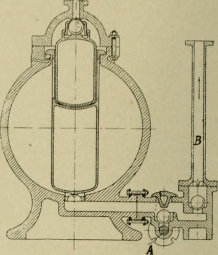
FIC. four.—EXHAf.STES.
Text Appearing Following Image:
coming tins difficully is to make the axle of the stirringnu-cbani..m hollow, and insert in its interior the driving shaft,the space among the driving axle and the interior surface ofilie hollow shaft I becoming filled with sulphur or concrete. Fig. J shows a centrifugal machine in which the quantity ofrevolutions of the driim is 800 pi r iiiiiiiite. the internal diam-eter of the stone-ware drum being850 mm. Ill or-der to defend thedrum a g a i 11 s Icracking, it is cov-ered with a man-tle of sheet steel.. 11 interestingconclusion frome.xaot calculationis that a mantleif cast iron wouldi()t do, becauseu h e 11 revolvingwith the sames|)eed the cast-iron mantle wouldexpand morethan the stone-ware drum. sothat the latter would not be protected. I lie liquid rises along the walls ofthe drum and is thrown (jver the rim into the outer casing, theinternal surface of which is also produced of stoneware. Thetop of .this casing consists of an opening for tilling and lateral pipes for sucking off acidva
Note About Images
Please note that these images are extracted from scanned page photos that could have been digitally enhanced for readability – coloration and look of these illustrations may not completely resemble the original function.
Image from page 448 of “Electrochemical and metallurgical sector” (1905)
Image by Web Archive Book Images
Identifier: electrochemicalm3190unse
Title: Electrochemical and metallurgical business
Year: 1905 (1900s)
Authors:
Subjects: Electrochemistry Chemistry, Technical Metallurgy
Publisher: New York : [Electrochemical Pub. Co.]
View Book Web page: Book Viewer
About This Book: Catalog Entry
View All Photos: All Images From Book
Click right here to view book on-line to see this illustration in context in a browseable on the internet version of this book.
Text Appearing Ahead of Image:
Text Appearing Soon after Image:
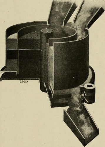
.MEASURING AND MIXING MACHINE. where each batch weighed might be diverse, provided that themeasuring apparatus does its perform accurately. Prior to the invention of the Trump measuring machine,measurement was not regarded sufficiently accurate, princi-pally due to the fact of inaccuracies introduced by the measuring de-vice itself. Rolls with pockets typically did not clear themselves completely, KLF.rTI^« M IIIMK l. AND M I- rAl.I.URGICAL Sector. (Vol. III. N… .1. .mil r.i a lot of situations have been alTicUii li llu <liiilli <ii m.iuriil inthe overhead hoppi-rs, wliich caused a variable density. Screw feeds wore to smaller sized diameters quite quickly withgritty suhstaiices. and so decreased the amounts fed out.With fine, powdery components they would Mmutimes flushthrough, regardless of the screw, and somelunes hang back.Even at its greatest the screw ilelivered pulsating feed. Years ago a device was invented consisting of a circularrevolving table, on which was a conical pile of material to bemeasured, th
Note About Images
Please note that these photos are extracted from scanned web page pictures that may possibly have been digitally enhanced for readability – coloration and look of these illustrations might not completely resemble the original operate.
Image from page 18 of “Electrochemical and metallurgical market” (1905)
Image by Internet Archive Book Images
Identifier: electrochemicalm3190unse
Title: Electrochemical and metallurgical industry
Year: 1905 (1900s)
Authors:
Subjects: Electrochemistry Chemistry, Technical Metallurgy
Publisher: New York : [Electrochemical Pub. Co.]
View Book Page: Book Viewer
About This Book: Catalog Entry
View All Photos: All Images From Book
Click here to view book on-line to see this illustration in context in a browseable on the internet version of this book.
Text Appearing Before Image:
the quantity of turns by a switching device,therefore varying the voltage of the secondary. A very good instance of the initial strategy is discovered at the worksof the International Acheson Graphite Company, where 750-kw. resistance furnaces are utilized. The present is supplied at2200 volts and is brought to a 25-cycle, 800-kw. transformerwhich delivers a secondary present at 140 volts. The regula-tor is a six-pole, 560-kw., 25-cycle apparatus with 140 volts pri-mary, and 60-volt, 9350-ampere secondary. By implies of theregulator the voltage of the existing delivered to the furnacescan be raised or lowered by 60 volts, therefore giving either 3740amperes at 200 volts, or 9350 amperes at 80 volts, or the cor-responding current at any intermediate voltage. The stick to-ing description of the regulator was kindly furnished to thewriter by Mr. W. S. Moody of the General Electric Co., whobuilt the apparatus. The punchings and windings of the regulator are assem-bled in a substantial oil-tight, cast-iron case getting a semi-
Text Appearing After Image:
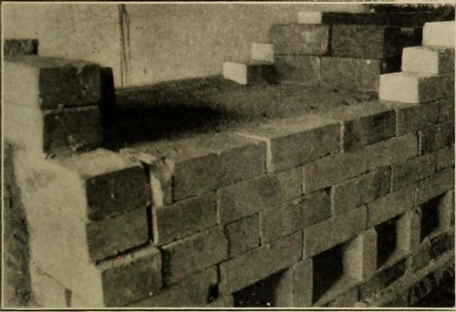
FIG. 4.—.RR.XGEMEXT OF RHEOST.XT. spherical cover which is made absolutely tight, so as to pre-vent dust and dirt receiving into the gearing and operatingmechanism. » Both the stationary and movable cores arebuilt up strong of very carefully annealed sheet-iron, supplied witha big quantity of slots for the winding. The windings con-sist of formed copper bars cautiously insulated and assembledin these slots. The ends of the windings_^ are brought out bymeans of versatile cables to a set of vertical bus-bars broughtthrough the center of the cover. In order to avoid an ex-cessive impedance in the device, and get as excellent a powerfactor on the program as feasible, the windings are sub-dividedand the bus-bars of each transformer and regulator are ar-ranged so that the alternate bars are of the exact same polarity.The sub-division of the regulator windings is obtained byconnecting all of the 6 poles of the machine in parrallel, andthe incredibly low impedance so obtained, collectively with theexceptionally
Note About Photos
Please note that these pictures are extracted from scanned page pictures that may have been digitally enhanced for readability – coloration and appearance of these illustrations may possibly not perfectly resemble the original function.
(Posted by a CNC machining China Company and precision CNC machined parts China manufacturer)
No comments:
Post a Comment